

Underground water tank buoyancy becomes a problem when the tank is empty and the groundwater is high: the water pushes up with a force equal to the weight of water the tank and slab displace. The flotation check divides everything holding the tank down by that uplift, and the ratio must reach a factor of safety, typically 1.3. LVJIA’s 72 m³ BDF example passes at 1.43, falls to 1.17 in a flood and floats if the pumps stop before the cover is placed.
At a glance
- Failure mode
- An empty buried tank lifting, tilting or shearing its pipes as groundwater rises
- Governing check
- Resisting weight ÷ uplift ≥ required factor of safety
- Uplift
- 9.8 kN/m³ × volume of tank and slab below the water table
- Resisting
- Tank self-weight, base slab, soil over the roof, soil on the slab toe, anchors if fitted
- Soil below water
- Counted at submerged unit weight, saturated minus 9.8 kN/m³
- Typical factors
- 1.3 usual, 1.2 unusual, 1.1 extreme (USACE EM 1110-2-2100)
- Worst moment
- Construction, after dewatering stops and before the cover is placed
- Tank range
- BDF composite plate, 1–1,000+ m³, heights 1–5 m
- Who designs the pit
- The site engineer; we supply the GA drawing and review the pit drawing
What causes underground water tank buoyancy?
A tank below the water table is pushed upward by a force equal to the weight of the groundwater it displaces, which is Archimedes’ principle. When the tank is full, its contents roughly cancel that push; when it is empty, only the tank, the slab and the soil above them are left to hold it down.
A 6 × 4 × 3 m tank fully below the water table displaces 72 m³ of water, about 706 kN of uplift at 9.8 kN/m³. Its BDF plate weighs roughly 25 kN at a 3 mm average thickness, about 3.5% of that uplift, so the concrete and the soil do almost all the work.
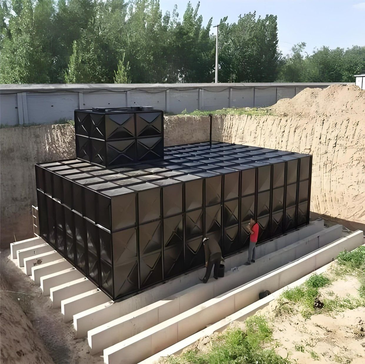
That is why an underground water tank is designed as a system: the panels resist water and soil pressure, while the pit, slab and cover resist flotation. Skimp on any one of those and the tank rises, tilts and tears its pipe connections.
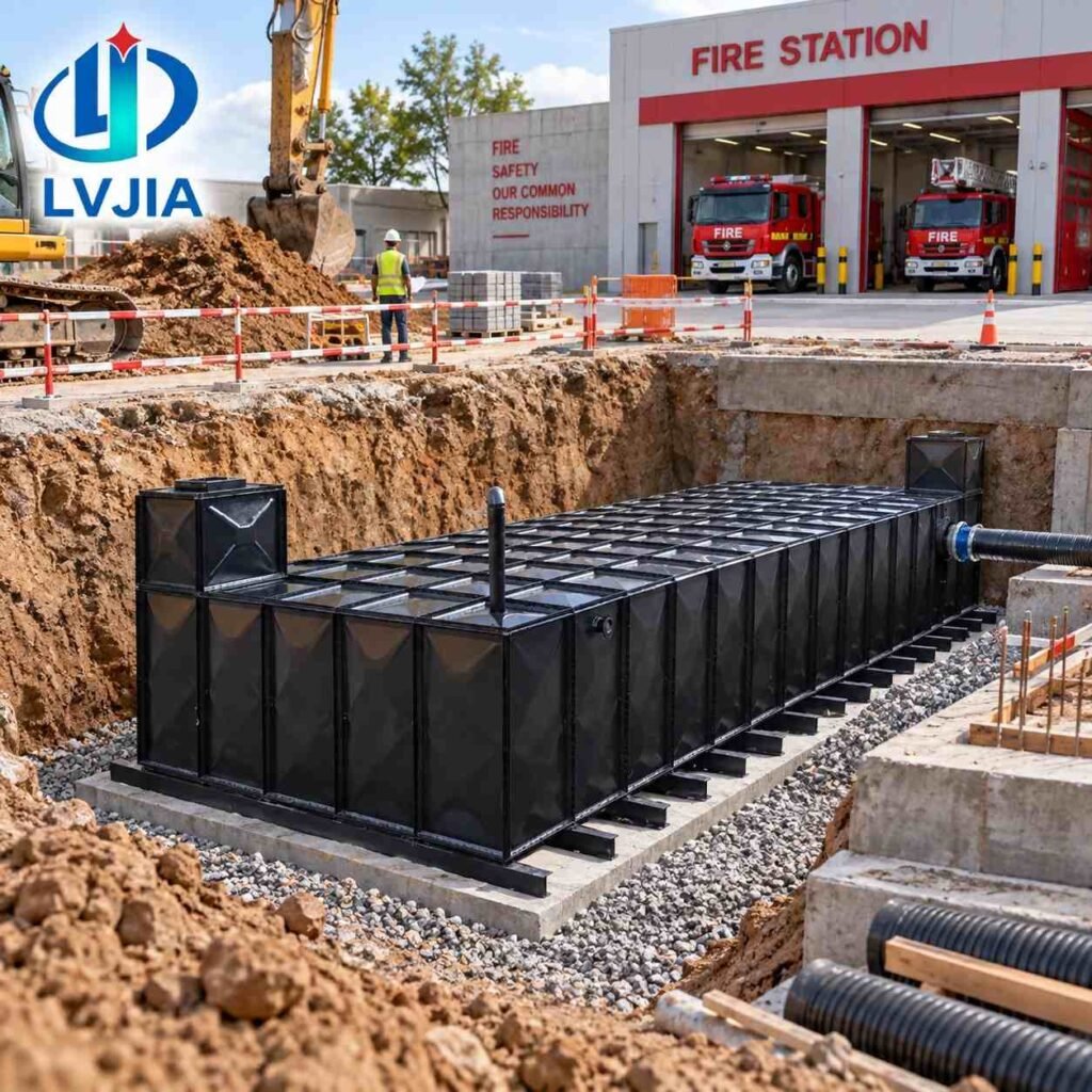
High groundwater is not the only trigger. Granular backfill in a clay pit collects surface water like a bathtub, and a burst main or a flood does the same.
How do you check underground water tank buoyancy?
Add up everything that holds the tank down, divide it by the uplift, and compare the ratio with the required factor of safety. Below the water table, soil counts at its submerged weight, because the water around it carries part of it.
Written out, the flotation check is FoS = (Wtank + Wslab + Wsoil, roof + Wsoil, toe + anchors) ÷ (γw × Vdisplaced), where Vdisplaced is the tank and slab volume below the design water level. The toe, the strip of slab projecting past the walls, matters because the soil standing on it lifts with the tank.
| Item | Value | Basis |
|---|---|---|
| Fresh water, γw | 9.8 kN/m³ | FHWA reference manual |
| Reinforced concrete | 25 kN/m³ | EN 1991-1-1, Table A.1 |
| Structural steel (BDF plate) | 77 kN/m³ | EN 1991-1-1, Table A.4 |
| Backfill above water, dry lower bound | 15.6 kN/m³ | Well-graded sand, loose, dry (FHWA Table 5-9) |
| Backfill, saturated | 19.5 kN/m³ | Well-graded sand, loose (FHWA Table 5-9) |
| Backfill, submerged | 9.7 kN/m³ | 19.5 − 9.8 |
γw and the soil values (Table 5-9) come from the FHWA Geotechnical Aspects of Pavements reference manual; concrete and steel are the EN 1991-1-1 densities in the EU Joint Research Centre’s Eurocode training material. Above the water table we use the dry value: moist soil is heavier, so the lower figure is conservative.
Worked example
Flotation check: 6 × 4 × 3 m BDF tank, 1.0 m cover, groundwater 1.0 m below grade, 7 × 5 × 0.3 m slab
- Displaced volume
tank 6 × 4 × 3 = 72.0 m³ + slab 7 × 5 × 0.3 = 10.5 m³82.5 m³, all below the water table - Uplift, U
9.8 kN/m³ × 82.5 m³ = 808.5 kN≈ 82 t upward - Tank self-weight
108 m² plate × 0.003 m × 77 kN/m³ = 24.9 kN3 mm average assumed, stiffeners and bolts ignored - Base slab
10.5 m³ × 25 kN/m³ = 262.5 kNfull weight; its buoyancy is already in U - Soil over the roof, above water
6 × 4 × 1.0 m × 15.6 kN/m³ = 374.4 kNroof sits at the water table - Soil on the toe, above water
(35 − 24) m² × 1.0 m × 15.6 kN/m³ = 171.6 kN0.5 m toe all round = 11 m² - Soil on the toe, below water
11 m² × 3.0 m × 9.7 kN/m³ = 320.1 kNsubmerged unit weight - Resisting total, R
24.9 + 262.5 + 374.4 + 171.6 + 320.1 = 1,153.5 kNno side friction, no anchors - Factor of safety
1,153.5 ÷ 808.5 = 1.43≥ 1.3 required for usual loading
Result: the tank passes at its design groundwater level. Raise the water to grade and every soil layer drops to 9.7 kN/m³: R falls to 947.0 kN and the factor to 1.17, below the 1.2 required for an unusual case. Leave the roof uncovered with dewatering off and R is only 607.5 kN, a factor of 0.75. The tank floats.
What factor of safety should an underground water tank buoyancy check reach?
The US Army Corps of Engineers requires 1.3 for usual loading, 1.2 for unusual and 1.1 for extreme. Eurocode 7 uses partial factors instead, and on our flood case the two approaches reach different verdicts.
Those factors come from Table 3-4 of EM 1110-2-2100, Stability Analysis of Concrete Structures, which counts the structure, fixed equipment and soil above the top surface as resisting weight. The Corps’ earlier ETL 1110-2-307 (1987) on flotation criteria says friction along the exterior faces should be neglected, and it set 1.3 for the construction case. We use the EM factors and leave friction out.
| Load case | Water level | Required | 0.5 m toe, 1.0 m cover | 0.75 m toe, 1.0 m cover | 0.5 m toe, 1.5 m cover |
|---|---|---|---|---|---|
| Usual: design groundwater | 1.0 m below grade | 1.3 | 1.43 pass | 1.79 pass | 1.64 pass |
| Unusual: flood to grade | At grade | 1.2 | 1.17 fail | 1.50 pass | 1.38 pass |
| Construction: roof uncovered, dewatering off | 1.0 m below grade | Do not allow | 0.75 floats | 1.01 floats | 0.75 floats |
For a European site, EN 1997-1:2004 checks uplift as a UPL limit state: destabilizing actions must not exceed stabilizing actions plus any resistance. The recommended partial factors, set out in the JRC’s Eurocode 7 worked examples, are 1.0 on destabilizing permanent actions and 0.9 on stabilizing ones. On our flood case that gives 0.9 × 947.0 = 852.3 kN against 808.5 kN, a pass.
So the same tank passes one method and fails the other. Where your jurisdiction names a method, use it; where it does not, we would design to the stricter, because extra concrete is cheap next to digging up a floated tank.
What do you change when the flotation check fails?
Add weight where it is cheapest, anchor the tank against uplift where weight is impractical, and control the water during construction. Never rely on water inside the tank as permanent ballast.
- Widen the slab toe. Going from 0.5 m to 0.75 m all round lifts the flood-case factor from 1.17 to 1.50, because each added square meter of toe carries a 4 m column of soil.
- Deepen the cover. 1.5 m of cover instead of 1.0 m gives 1.38 in flood, at the cost of a deeper dig and taller manhole risers.
- Thicken the slab. Each extra 100 mm on the 7 × 5 m slab adds 35 × 0.1 × (25 − 9.8) = 53.2 kN net, because added concrete below water also adds uplift.
- Anchor the tank. Straps or hold-downs tied to cast-in points take the shortfall. In flood the example is short by 1.2 × 808.5 − 947.0 = 23.2 kN, a small anchor load.
- Never leave the tank empty in high water. Each 100 mm of water inside adds about 24 m² × 0.1 m × 9.8 kN/m³ = 23.5 kN, so schedule cleaning and inspection for the dry season.
Watch out
Water ballast is an operating measure, not a design weight. In our example, holding the uncovered tank at 1.3 would need about 1.9 m of water inside: (1.3 × 808.5 − 607.5) ÷ (24 m² × 9.8 kN/m³). That is a tank nearly two-thirds full that nobody may drain until the cover is on.
What must the pit and excavation drawing show?
It must show every weight the flotation check relies on and every level it assumes, so the site builds what was calculated. Anything left off, such as the minimum cover or when the pumps may stop, gets decided on site by someone who never saw the calculation.
| Drawing item | What it must show | Why it matters |
|---|---|---|
| Excavation plan and section | Pit size, side slopes or shoring, formation level, working space | Cave-in protection for anyone working inside |
| Water levels | Design groundwater, flood level, level held during construction | The flotation check is only as good as these three lines |
| Base slab | Plan size, toe width, thickness, reinforcement, cast-in anchor points | The toe and slab weight carry much of the resistance |
| Tank setting-out | External dimensions and datum from our GA drawing | Toe width is measured from the tank wall, not the pit edge |
| Backfill | Material, compaction method, placement sequence on all sides | The check assumed a unit weight; uneven filling loads walls unevenly |
| Cover | Minimum soil depth over the roof, finished levels | Landscaping later must not reduce it |
| Manhole risers and vent | Riser heights to finished level, vent terminal and screen | Access for inspection; the vent stops pressure and vacuum on the roof |
| Pipe entries | Positions from our drawing, flexible couplings at the wall | Small settlement or movement must not shear a rigid pipe |
| Traffic | No-traffic zone, or a separately supported load-relieving slab | Wheel loads must not reach the roof panels |
Excavation safety belongs on the same sheet. In the United States, OSHA’s 29 CFR 1926.652(a)(1) requires a protective system against cave-in unless the excavation is entirely in stable rock, or is less than 5 feet (1.52 m) deep and a competent person finds no sign of a potential cave-in. Our example pit is about 4.3 m deep, so anyone working in it needs that protection.
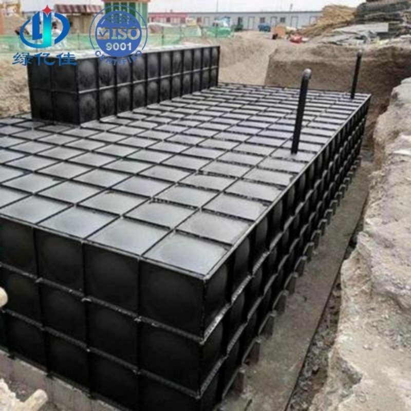
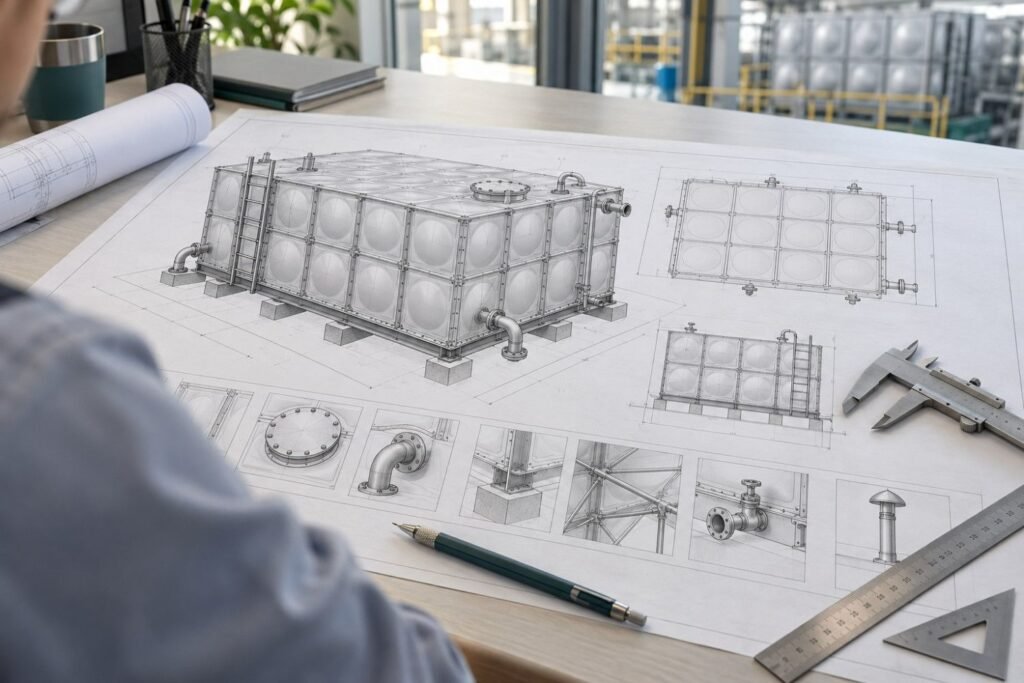
How should installation be sequenced to keep the tank down?
Keep the water table below formation from the first dig until the full cover is placed, and add weight in the order the flotation check assumes. The riskiest hours fall between setting the tank and finishing the cover.
Start dewatering and confirm the water table is below formation before excavating to it.
Excavate to the drawing with the slopes or shoring shown, and keep water off the formation.
Cast the base slab with its full toe and any cast-in anchor points, to the level tolerances on the drawing.
Bolt the BDF panels up on the slab with the rubber sealing strips, and fit straps if the design uses them.
Fill and hold the tank for a leak test while every joint can still be reached. The water also holds the tank down.
Place and compact backfill on all four sides together, so no wall is loaded far ahead of the others.
Bring the soil over the roof to the full design depth and set risers to finished level.
Only now switch the dewatering off, and record the date and the groundwater level.
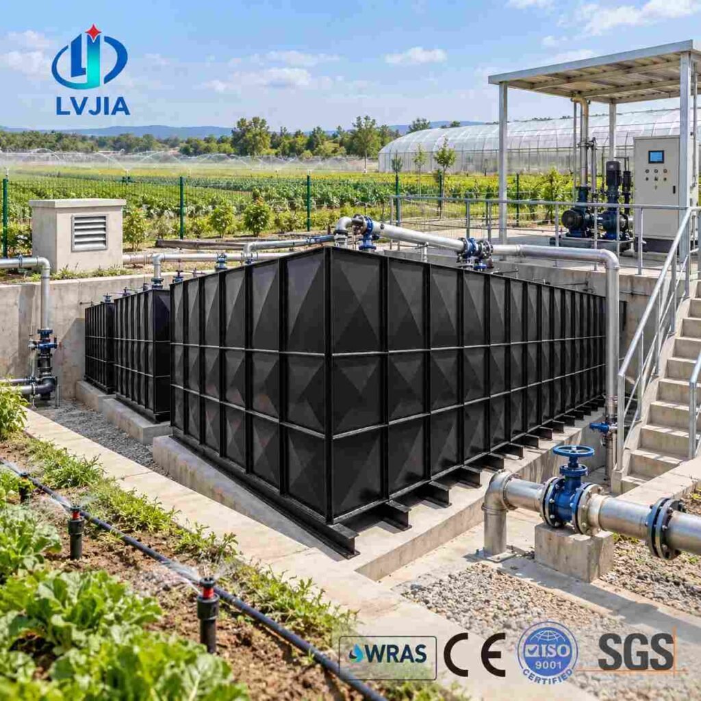
Where do flotation failures come from?
Almost never from the tank panels, and almost always from a change between the calculation and the site. These are the causes we would look for first on a tank that has moved.
- Dewatering switched off before the cover was placed.
- The tank drained for cleaning or inspection while the water table was high.
- Cover reduced later by landscaping, paving or a new access road.
- A slab toe cut back on site to fit a boundary or a service trench.
Watch out
A partly lifted tank rarely settles back level. Soil runs in under the slab as it rises, so the tank stays tilted, with sheared pipes, after the water drops.
What do the standards say, in plain language?
No standard we know of gives a flotation rule written for bolted steel tanks, so designers borrow from structural and geotechnical practice. The Corps of Engineers manual gives the factors, Eurocode 7 gives a partial-factor route, and the unit weights come from load and soil references.
The two routes differ on side friction: the Corps letter neglects it, while the Eurocode 7 worked examples count it, reduced by a model factor of 0.8, where it can be justified. None of these documents is a product standard for the tank, so the pit design stays with the site engineer who knows the ground and the local code.
How does LVJIA handle buoyancy on the drawing and at the works?
We supply the tank data the flotation check needs and review the pit drawing against our panel layout before anything is pressed. The slab, anchors and excavation are designed by the site engineer, because they depend on ground data only the site has.
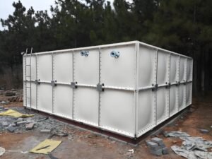
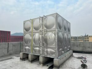
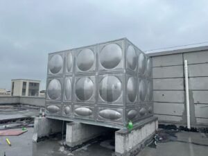
Our BDF tanks are built from bimetallic composite plate of stainless steel and galvanized steel, from 1 to 1,000+ m³ and 1 to 5 m high, with walls 2–5 mm thick by height. There are no welded parts in contact with water; joints are sealed with rubber strips and bolts.
Every tank is trial-assembled and water-tested for 48 hours at our works before it is stripped and crated. You can see the route on our page about how we press and test BDF panels. The BDF range also carries drinking-water contact report SP2630499 to GB/T 17219-2025.
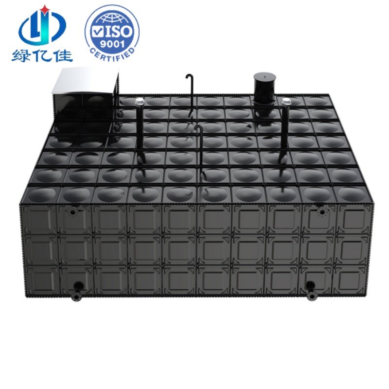
Send the pit drawing with the tank drawing and our engineers return it as a marked-up PDF within one working day, free of charge. Models to start from include the anti-floating BDF fire water tank, the heavy-duty BDF fire water tank, the BDF rainwater storage tank and the two-compartment fire and rainwater tank. Dimensions are in our BDF datasheets and CAD blocks.
Underground water tank buoyancy checklist
Run through this list before the pit drawing is issued for construction. Each line marks a point where a change on site can undo the calculation.
- Design water table, flood level and the level held during construction, all stated on the drawing.
- Uplift on tank plus slab volume, soil below water at submerged weight, no side friction.
- Factor of safety checked for usual, unusual and construction cases against the code that applies.
- Slab toe, slab thickness and minimum cover dimensioned, with a note that the cover must not be reduced later.
- Anchor points and straps shown where used, and sent to us with the pit drawing for review.
- Flexible couplings at every pipe entry, a screened vent, risers to finished level, and traffic kept off the roof.
- Dewatering kept running until the cover is compacted; the tank never drained in high groundwater.
Underground water tank buoyancy: frequently asked questions
Does a tank that is always kept full need a flotation check?
Yes. Tanks are drained for cleaning, for repairs and sometimes for a change of use, and a fire reserve can be emptied in a single event. The check therefore assumes the tank is empty at the highest groundwater the site can see; any water inside is a margin you enjoy but never count.
Can I count the friction of the backfill against the tank walls?
We would not in a backfilled pit. Freshly placed fill is loose and often wet at exactly the time uplift peaks, so the friction you calculate may not exist when you need it. On a tank you want to keep for decades, the margin is better placed in slab concrete, toe width or cover depth, which do not depend on how well the fill was compacted.
What if groundwater is well below the tank?
Then flotation from the natural water table is unlikely, but check for perched water. A granular surround in clay can fill from rainfall and float a tank that sits meters above the true water table. A drain from the pit base to a lower outfall, or an impermeable cap over the backfill, removes that risk.
Where should anchor straps sit on a BDF tank?
Where your engineer’s uplift shortfall needs them and where the tank can take the load. Hold-downs belong to the site design, so tell us which system is proposed while our drawing is still open for approval. Straps, cast-in points and nozzles then appear on the same drawing set, and clashes are found on paper rather than in the pit.
Can vehicles drive over a buried BDF tank?
We do not publish a traffic rating for BDF tank roofs. If the tank sits under a car park or access road, your structural engineer should design a load-relieving slab supported beyond the tank on its own bearing, so wheel loads never reach the roof panels. Otherwise fence or mark the area as a no-traffic zone.
What ground data does the flotation check need?
At least three water levels: the design groundwater level from monitoring, a flood or extreme level, and the level you will hold during construction. Add the unit weights of the backfill you will actually place, and a note on whether the pit sits in clay that could trap perched water. A site investigation with seasonal readings beats a single borehole reading taken in a dry month.
Talk to an engineer
Send us the pit drawing with the tank
Give us the tank size, the groundwater levels and your slab design. You get the drawing back as a marked-up PDF within one working day, free.